Introduction
This document provides an overview of Salesforce entity relationship diagram (ERD) notation and conventions to help you clearly interpret the product data models now available in the architecture gallery at architect.salesforce.com.
An ERD, also known as a data model, is a graphical representation of an information system. It shows the relationships among people, objects, places, concepts, and events in that system. It is a logical model that conveys the functional structure of data. In Salesforce ERDs, entities typically map to an object in the Salesforce database.
Modified Information Engineering Notation
Salesforce ERDs use a modified form of the Information Engineering (IE) notation. The Information Engineering notation was invented with the work of Clive Finkelstein in Australia and CACI in the United Kingdom, and was later adapted by James Martin. Different versions of IE exist, with no single standard, but IE is supported by many data modeling tools and is one of the most popular notations for database design. (Source: Information Modeling and Relational Databases, 2008 by Terry Halpin and Tony Morgan.)
Entities
An entity is a thing or object of significance, whether real or conceptual, about which information needs to be known or held.
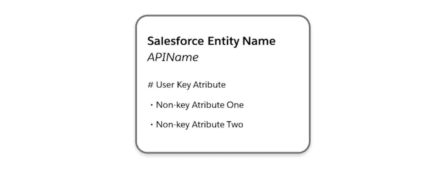
Entities are represented in the diagrams as boxes with rounded corners. Each entity box typically provides two labels (where applicable):
- The logical name of the entity (e.g. “Salesforce Entity” in the example shown here). This may correspond to the singular label of the represented Salesforce object, but not always.
- The “physical” API Name or Developer Name of the object in your Salesforce organization (e.g. “API Name” in the example). For managed package objects, the API name listed in the diagram typically does not include the managed package namespace (“vlocity_ins**”, for example) unless the Salesforce or Industry cloud uses multiple managed packages. The end of the API name for managed package objects denotes the type of custom object used: “**c” for regular custom objects and custom settings, “**mdt” for custom metadata, “**x” for external objects.
Entity boxes may also list one or more attributes that are representative of the attributes of that entity. An attribute is preceded by either a “#” or a “-” character.
- A “#” indicates an attribute that is part of the logical unique key of the entity. In the example diagram, “User Key Attribute” is considered the user primary key of the entity.
- A “•” indicates a non-key attribute.
Entity Formatting
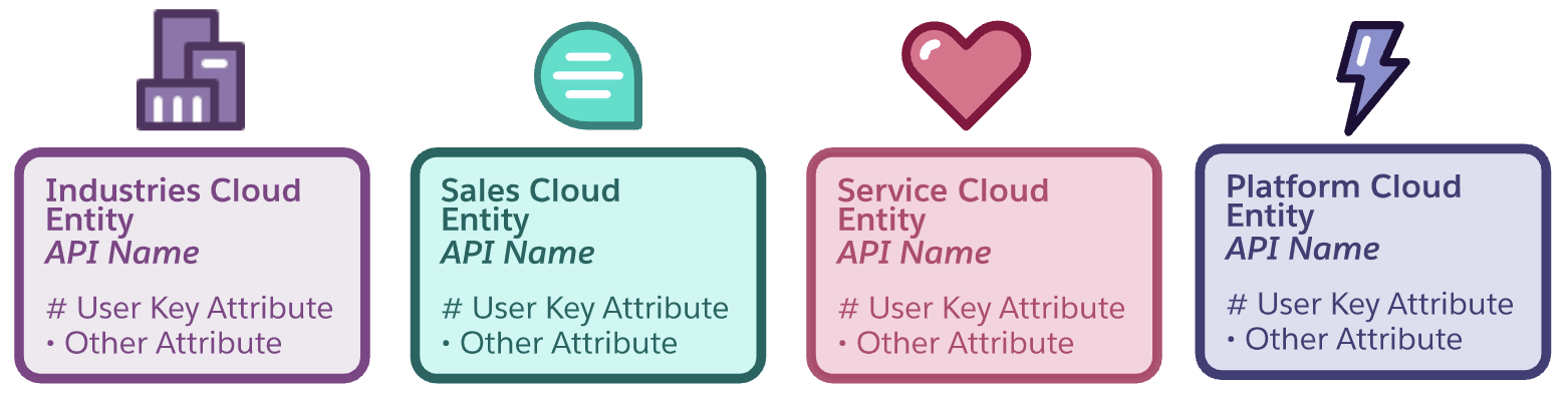
Each entity relationship diagram illustrates the Salesforce data model from the perspective of a specified cloud such as Sales Cloud, Service Cloud, or Marketing Cloud. The color scheme of the diagram reflects the cloud in focus. All industry clouds such as Financial Service Cloud, Health Cloud, and Media Cloud use a the same Industry color scheme.
The color of a given entity on the diagram also has a specific meaning. The focus cloud color is indicated using its Salesforce branded color, including some examples below.
The following section will review the different entity formatting referring to the Sales Cloud example legend below:
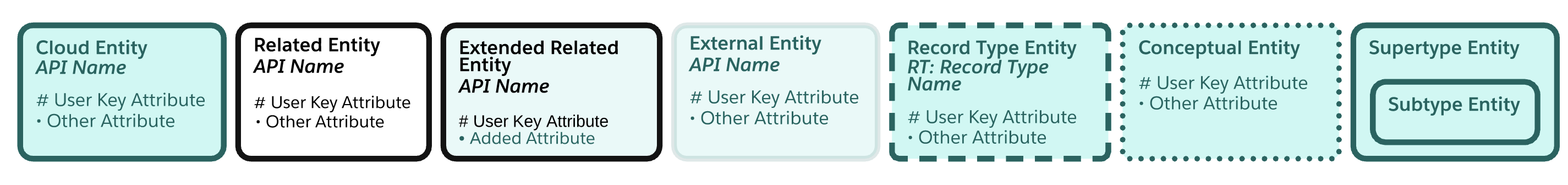
Cloud Entity
An entity with the colors of the focus cloud represents an object that comes with the license for that cloud.
Related Entity
An entity with a white fill and black border represents an object that comes with a different license than the focus cloud and that is not extended by the focus cloud license. Account and Contact entities shown on a Sales or Service Cloud ERD, for example, will be shown as white with a black border since those objects are available with a platform license.
Extended Related Entity
An entity with a light gray fill and black border represents an object that comes with a different license than the focus cloud, but the focus cloud extends that object. For example, Commerce Cloud extends the base Product2 object with additional fields. Extensions include additional fields, relationships, and record types.
External Entity
Entities with no borders are virtual. When used in a diagram, these boxes acknowledge the existence of an entity in the logical model for the domain, but the entity is not implemented as a physical object in Salesforce. The data for this entity is expected to be accessed via external API calls or Salesforce Connect in the deployed solution.
Record Type Entity
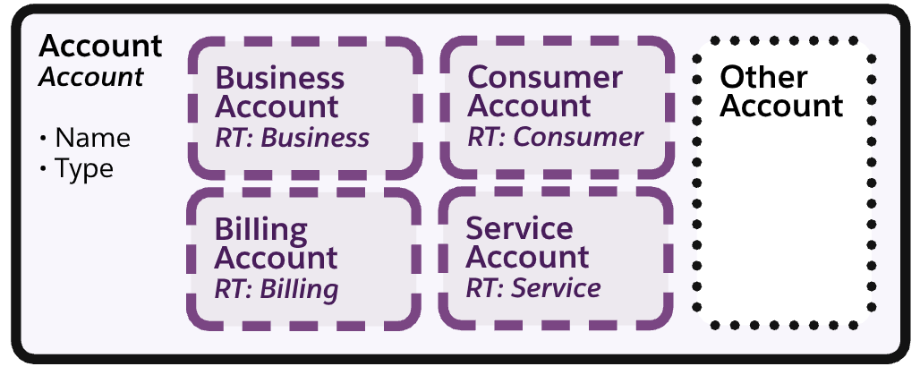
Entities with a dashed border are modeled as record types in Salesforce. In the example shown here, the Business Account, Billing Account, Consumer Account and Service Account subtypes have a dashed border because they map to record types delivered with the Communications Cloud managed package.
Conceptual Entity
Entities with a dotted border are virtual. Neither record types nor a separate object are used to differentiate these subtypes in the Salesforce solution. These subtypes logically depict a concept from the domain that helps to illustrate the functionality of the data model.
Supertype and Subtype Entities
A subtype of an entity is the definition of a subset of its occurrences. When a set of subtypes is added within a supertype entity, the supertype entity depicts the common attributes and relationships while the subtype entities show attributes and relationships specific to the subtype. In the diagram notation, subtypes are mutually exclusive, meaning that any single record must be of a single subtype.
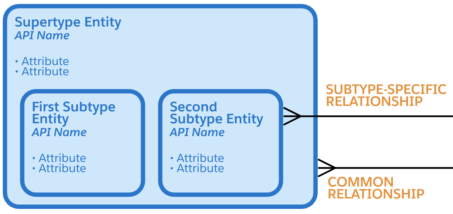
Subtypes can have nested subtypes that further differentiate the occurrences. Subtypes in the diagrams are logical but they can map to a physical representation in one of three ways. The solidness of the subtype entity border defines how the subtype is implemented in the Salesforce data model.
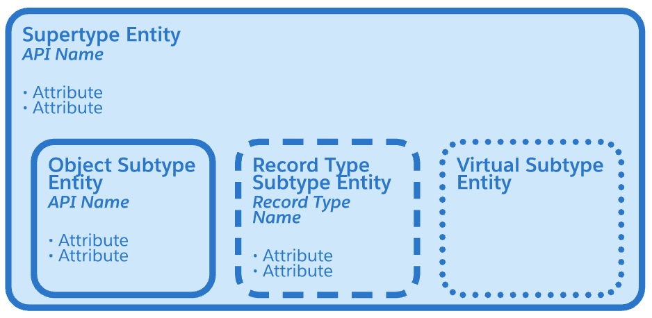
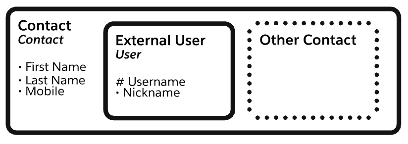
Subtype entities with a solid border have an actual object that tracks the occurrences of that subtype. In the example shown here, the External User subtype of Contact has a solid border because Contacts that are registered as External Users are tracked with a record in the User object.
Relationships
A relationship is a named, significant association between two entities.
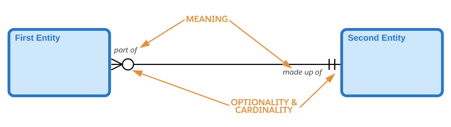
The markings and text on or around the lines describe the cardinality, optionality, and meaning of the relationship.
Relationship Cardinality
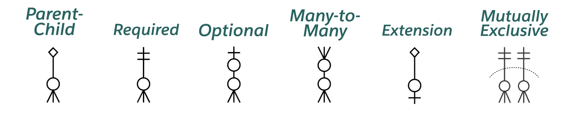
Cardinality indicates the relative numbers of occurrences on each side of the relationship. In the notation, the ends of a relationship line indicate the cardinality of the relationship on that end. A crow's foot on an end indicates that many entity occurrences on that end can relate to each occurrence on the opposite end. The lack of a crow's foot on an end indicates that at most one entity occurrence on that end can relate to a given occurrence on the other end.
Parent-Child Relationships
Salesforce supports two kinds of relationship fields: lookup fields and parent-child (aka master-detail) fields. Parent-Child fields are like required lookups but they apply additional coupling between the related entities. Records on the many side of the relationship are cascade-deleted when the parent record is deleted. Also the visibility of the detail records is controlled by the visibility of the parent record.
To illustrate the difference between a child-parent relationship and a lookup relationship, Salesforce ERDs borrow the diamond notation from UML. A diamond on the singular side of a relationship means that the entity on that side plays the master role in the relationship. The entity on the many side of such a relationship is the detail or child entity and can be thought of as contained within the parent entity.
Relationship Optionality
Optionality indicates whether the relationship is required or not for an occurrence on each end. As a concept, optionality is closely related to cardinality and the notation reflects that closeness. Optionality is indicated at each end of a relationship through a circle or bar across the line on the other end of the relationship. Why on the other end of the relationship? To include the optionality mark-up on the same side of the line as the cardinality.
On the many (that is, crow’s foot) side of the relationship, there is almost always a circle on the line. This means there can be zero-to-many occurrences on the many side of the relationship for each occurrence on the singular side of the relationship.
On the singular side of the relationship, a circle and a bar indicate an optional relationship for the entity on the crow’s foot side of the relationship. The circle and bar mean there can be zero or one occurrences on the singular side of the relationship for each occurrence on the many side.
Alternatively on the singular side of the relationship, double bars indicate a required relationship for the entity on the many side of the relationship. The double bars mean there must be one and only one occurrence on the singular side of the relationship for each occurrence on the many side.
The optionality of a relationship may be shown as required even though the underlying physical relationship in Salesforce is optional. For example, the AccountId field on Contact is physically an optional relationship, but if you ignore Private Contacts, the direct relationship of a Contact to an Account is logically required. The optionality indicator is used sparingly. In most cases, the optionality shown in the ERD reflects the underlying optionality of the relationship.
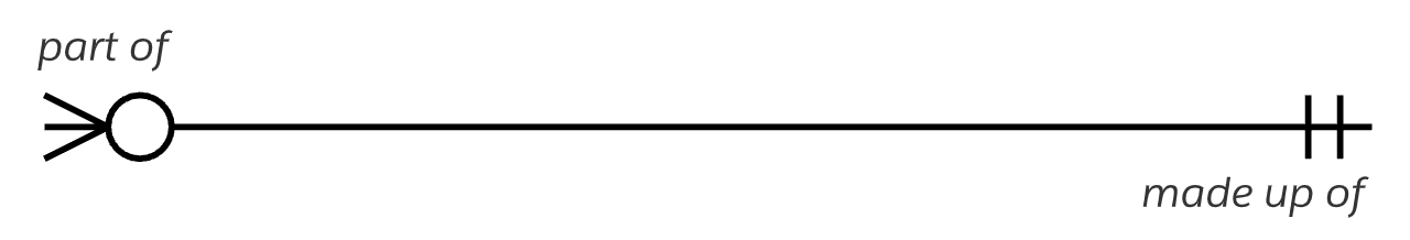
Relationship Meaning
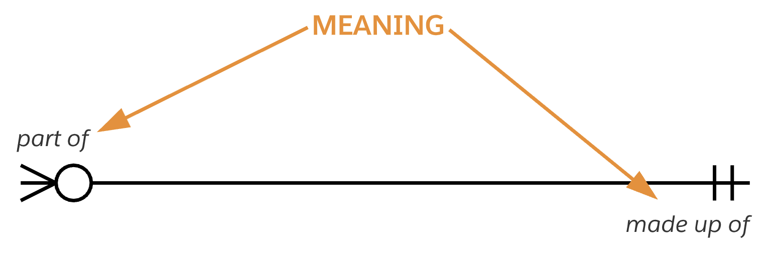
Beyond cardinality and optionality, each relationship between two entities expresses a certain meaning that distinguishes that relationship from other relationships between the same two entities. Relationship end names, such as “part of” and “made up of” in the diagram above, define the nature of the relationship.
When you combine the cardinality, optionality, and end names of a relationship, they can be used to form a sentence that describes the relationship.
From left to right: Each
From right to left: Each
For example,
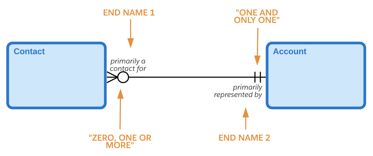
From left to right: “Each Contact must be primarily a contact for one and only one Account.” From right to left: “Each Account may be primarily represented by one or more Contacts.”
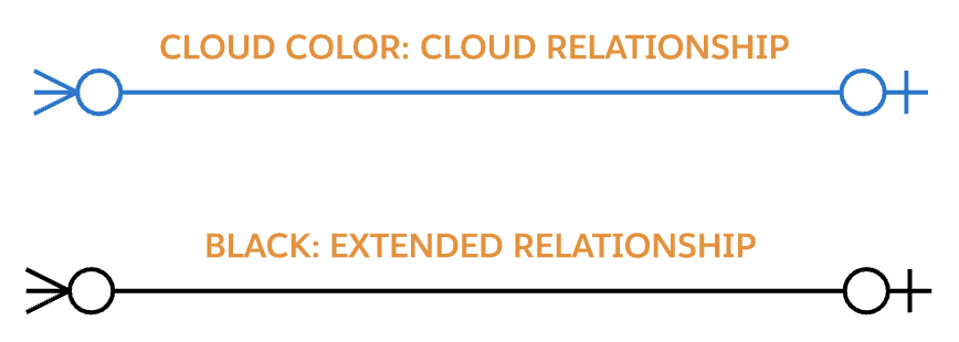
Relationship Color Coding
Relationship lines are color-coded. Relationships added by the cloud in focus for the diagram are drawn in a color. Black lines represent a relationship that comes with a different license than the focus cloud.
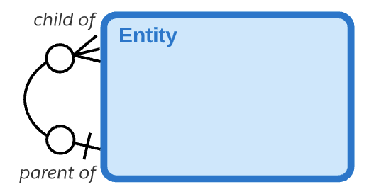
Recursive Relationships
Relationships can be between two occurrences of the same entity. This is called a recursive relationship. A curved relationship line is used to denote recursive relationships.
Mutually Exclusive Relationships
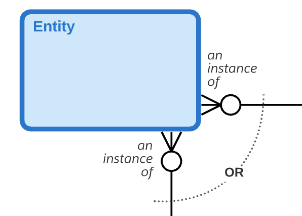
Salesforce ERDs typically exclude most business rules in order to focus on the structure of the data model, but a mutually exclusive relationship is one business rule that is informative to the structure so it is noted. A mutually exclusive relationship indicates that only one of the several relationships included in the arc will be used for any given occurrence. Note that two, three, or more relationships can participate in the same mutually exclusive relationship. A sentence that describes the mutually exclusive relationship shown here could be: “Each Entity may be an instance of one and only one First Other Entity or one and only one Second Other Entity.”
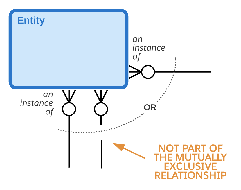
Note that in the Salesforce ERDs, a broken relationship line that passes through the arc is not a part of the mutually exclusive relationship.
Layout Conventions
Official Salesforce product ERDs follow layout conventions to improve readability. These layout conventions include the following:
- Relationship lines should always be straight.
- Relationship lines should be drawn vertically or horizontally. In rare occasions where this is not possible, use a straight line on a diagonal.
- In order to keep relationship lines straight, entity boxes can be resized (taller or wider) to provide a landing place for the relationships between the two entities. The more important entities (which have more relationships landing on them) are shown larger on the diagram reinforcing their importance.
- Throughout a single ERD, the crow’s feet on relationships should be consistently on the left-side and/or top-side of the relationship line (upside-down layout) – or consistently on the right-side and/or bottom-side of the relationship line (right-side-up layout). This convention provides clarity as it results in similar entities gathered in the same area of the diagram, which is helpful for understanding the entities. Using the upside-down layout does result in diagrams appearing upside-down with child entities falling above or to the left of parent entities – however, this ensures that the most specific entities in the diagram fall in the top-left corner of the diagram, which makes the diagrams easily recognizable. Using the right-side-up layout convention results in the same common entities falling in the top left of every diagram, but child entities will be below or to the right of parent entities.
Close adherence to these layout conventions results in a clean and easy-to-read diagram.
Be sure to check back regularly on the template gallery at architect.salesforce.com for the latest Salesforce product data models that follow this standard.